Tapered Members
Tapered members are typically composed of separate parts making up the flanges and web. They are then welded together to make a single member. In the case of a tapered I beam, the top and bottom flanges are welded to the tapering web component. The web is the only part of the member that is tapered. The flange cross sections are constant throughout the tapered member.
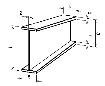
STAAD.Pro defines tapered members as a collection of dimensions.
Accordingly, the STAAD.Pro syntax for tapered I sections is:
- 1 TAPERED f1 f2 f3 f4 f5 f6 f7
- f1 = Depth of section at start node
- f2 = Thickness of web
- f3 = Depth of section at End node
- f4 = Width of top flange
- f5 = Thickness of top flange
- f6 = Width of bottom flange. Defaults to f4 if left out
- f7 = Thickness of bottom flange. Defaults to f5 if left out
Because a tapered member is typically constructed from separate plate elements welded together to create a beam, Structural discipline supports a section type named PlateGirder. Plate girder section definitions are mapped to the STAAD.Pro tapered member's start and end section using the following syntax:

Plate girder XML section definition file syntax to map incoming STAAD.Pro tapered member. Please note only the first dimension varies (d) for section depth.
If the sections Tapered Plate 1 and Tapered Plate 2 (described in the syntax example above) are used to create a tapered member in Structural discipline, and then exported to STAAD.Pro, the STAAD.Pro syntax becomes:
1 TAPERED 1.5 0.15 1.25 1.16667 0.25 0.833333 0.25